


Gear Pump : What is Gear Pump ; Working Principle & Industrial Applications

Gear pump is considered as one of the most important types of pumps among all hydraulic fluid transfer pumps. These types of pumps uses gear mechanism for the transportation of fluids. The Gear pump was invented by Johannes Kepler in 1600 around.
Let see the Basics of Gear Pump first.

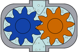
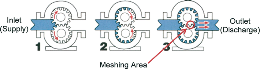
Gear pumps fall under the category of positive displacement pumps (rotary pumps). In general gear pump encloses a fixed volume of fluid by the help of interlocking cogs or by meshing of gears and applies mechanical force / pressure energy on that entrapped volume. The pumping action is a continuous cyclic process. In this manner the movement of fluid takes place.
- For handling high viscous fluid gear pump is used frequently in the industry.
The size of the the pump is relatively small compared to other hydraulic pump. It is considered as high pressure pump which not only provides a pulse-free flow but also provides stable and continuous flow facility.
There are three types of Gears mainly used in Gear Pump:
- Spur Gear
- Helical Gear
- Herringbone Gear
Some of the high advantage / application of this pump is:
- Considered as self primed pump
- Can handle high viscous fluid
- Easy to operate, handle & maintenance
- Generally used for the transportation of paint, ink , resins, adhesive, pulp ; frequently used in petrochemical, pharmaceutical & Food industries.

Working of Gear Pump :
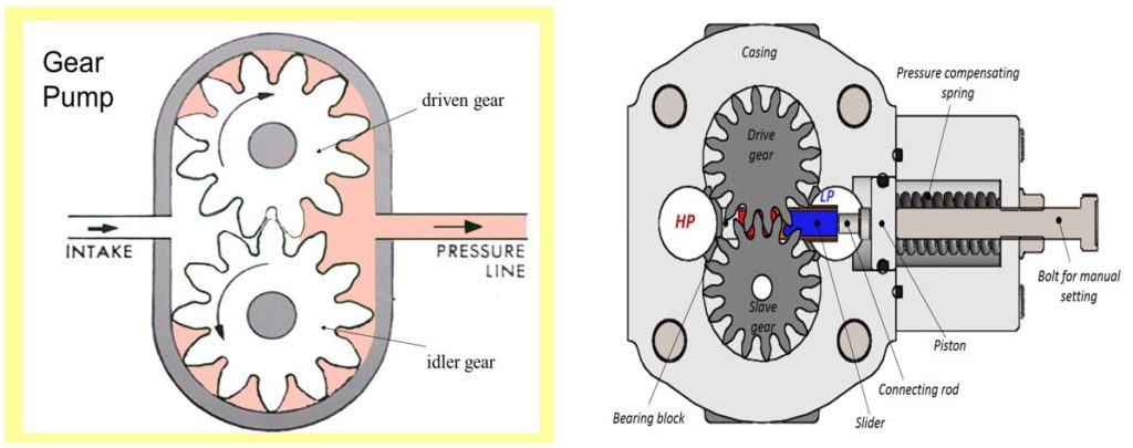
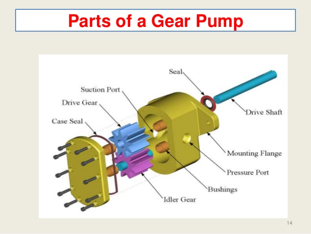
In general a gear pump consist of two spur gears which meshes together and revolves in opposite directions within a casing. The transfer of fluids in gear pump takes place with the help of gears. As the gear rotates the separation of fluid takes place at the inlet port of the pump, which also helps in creating voids and suction which gets filled by working fluid. With the help of these gears or due to this rotating mechanism only displacement of fluid takes place and fluid gets discharged. The spacing between the gear teeth and the pump housing is very fine ( is the order of 10 µm).
Note :
- For the safety of pump a relief valve should be fitted at the discharge section of the pump.
- The casing plays a very vital role in case of Gear Pumps. The close clearance ( clearance is of generally few thousandths of an inch) between casing and the teeth of gear pump decides the pressure (discharge pressure ) developed.


Types of Gear Pump
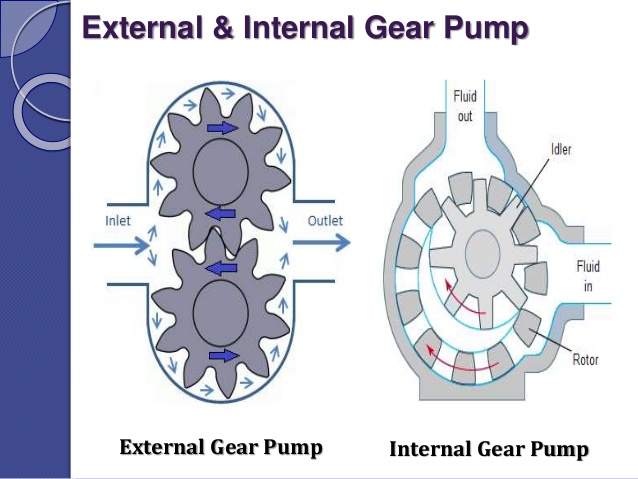
There is mainly two types of Gear pumps, classified on the basis of its Design Aspects.
- Internal Gear Pump
- External Gear Pump
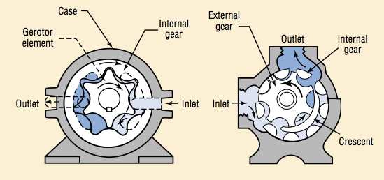
Internal Gear Pump :

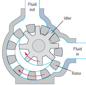
In an internal gear pump fluid enters int the suction port between the rotor and idler( it is a small interior gear) teeth. The fluid travel through the pump between the the teeth of the “gear-within-a-gear” principle.Liquid enters the suction port between the rotor (large exterior gear) and idler (small interior gear) teeth. The arrows indicate the direction of the pump and liquid. The crescent shape divides the working fluid and acts as a seal between the suction and discharge ports. Now the pump head completely flooded. The intermeshing gears of the idlers and rotor forces the liquid outward and thus the displacement of fluid takes place.
Features :
- Having Only Two Moving Parts
- Can run dry also for a very short span
- Low NPSH is required
- Zero Pulsating Discharge
- Easy to operate, maintain.
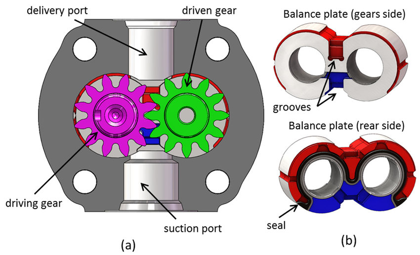
External Gear Pump :
This gear pump uses two external gears with external cut teeth for the displacement of fluids. This type of pump is very cheap, easy to handle and operate.
Features :
- Compact Size and Easy Design
- Can deliver high capacities
- High Speed, High Pressure.
Article Source : Wikipedia