


How you can design a Heat Exchanger ?
This is frequently asked question in many of the interviews ! Heat Transfer is an important operation whatever the industry( e.g chemical industry, Pharmaceutical industry, Bio Pharma ..many more ) you talk about . Heat Transfer means there is the exchange of thermal energy takes place between two bodies / fluids due to the presence of thermal gradient, when they comes in contact . Designing a heat exchanger is very crucial so that efficiently heat transfer can takes place.
Let see first in a brief about the classification of Heat Exchangers.
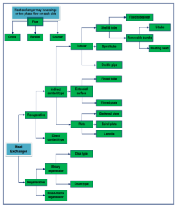

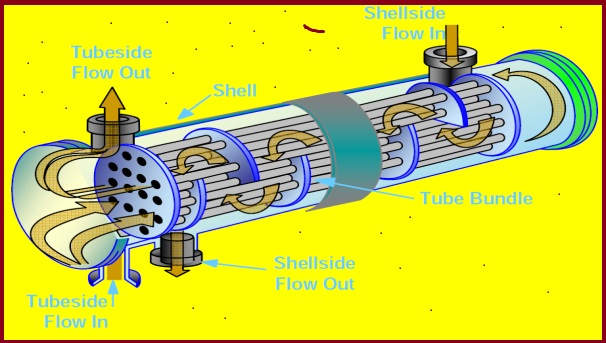
Among all Shell and Tube type heat Exchangers are frequently used one.
Shell and Tube type heat Exchangers are classified into :
- Fixed Tube Sheet heat exchangers
- Removable Tube Bundle
Removal Tube Bundle are further sub-categorized as :
1) U Tube type heat exchanger

2) Floating head type heat exchanger


Below mentioned Schematic is the split view of Floating Head Heat Exchanger
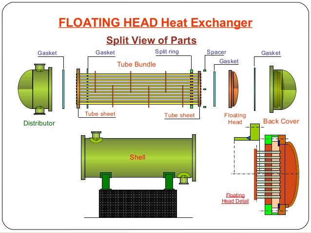

Source : https://www.slideshare.net
The design of a heat exchanger addresses mainly three phases:
- Thermal Design Considerations


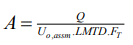
Where,
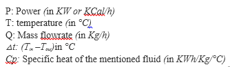

Example: application for cooling water at a flowrate of 10 m3/h

In order to calculate Tout ; By using of the above mentioned formulas we can calculate it as ..mentioned below :
![]()

i.e Tout = 73 °C
Total power: 65,000 KCal/h or 756 KW
Shell and tube heat exchanger is designed by trial and error calculations.
The main steps of design following the Kern method are summarized as follows:
Step #1. Obtain the required thermophysical properties of hot and cold fluids at the
caloric temperature or arithmetic mean temperature. Calculate these properties at the
caloric temperature if the variation of viscosity with temperature is large.
Step #2. Perform energy balance and find out the heat duty ( Q ) of the exchanger.
Step# 3. Assume a reasonable value of overall heat transfer coefficient (Uo,assm).
Step #4. Decide tentative number of shell and tube passes (p n). Determine the LMTD
and the correction factor FT . FT normally should be greater than 0.75 for the steady operation of the
exchangers. Otherwise it is required to increase the number of passes to obtain higher FT
values.
Step #5. Calculate heat transfer area (A) required:

Step #6. Select tube material, decide the tube diameter (ID=i d, OD =o d), its wall thickness (in terms of BWG or SWG) and tube length (L). Calculate the number of tubes(t n) required to provide the heat transfer area (A) is
![]()

For calculating tube side fluid velocity, 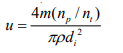
this is subject to allowable pressure drop in the tube side of the heat exchanger.

Step #7. Decide type of shell and tube exchanger (fixed tubesheet, U-tube etc.). Select the tube pitch (PT), determine inside shell diameter (Ds) that can accommodate thecalculated number of tubes (t n). Use the standard tube counts table for this purpose.
Step #9. Assign fluid to shell side or tube side . Select the type of baffle (segmental, doughnut etc.), its size
(i.e. percentage cut, 25% baffles are widely used), spacing (B) and number. The bafflespacing is usually chosen to be within 0.2Ds to Ds.
Step #10. Determine the tube side film heat transfer coefficient (i h) using the suitable form of Sieder-Tate equation in laminar and turbulent flow regimes.
Estimate the shell-side film heat transfer coefficient ( ho) from:
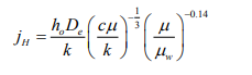

You may consider,
![]()

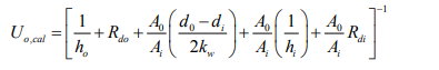
Select the outside tube (shell side) dirt factor (Rdo) and inside tube (tube side) dirt factor(Rdi).
For Calculating overall heat transfer coefficient (Uo cal ,) based on the outside tube area (you may neglect the tube-wall resistance) including dirt factors:

Step #11. Calculate the tube-side pressure drop (ΔPT): (i) pressure drop in the straight section of the tube frictional loss) (ΔPt) and (ii) return loss (ΔPrt) due to change of direction of fluid in a „multi-pass exchanger‟.
Total tube side pressure drop:
![]()

Step #12. Calculate shell side pressure drop (ΔPS): (i) pressure drop for flow across the tube bundle (frictional loss) ( ΔPs ) and (ii) return loss ( ΔPrs ) due to change of direction of fluid.
Total shell side pressure drop:
![]()
If the tube-side pressure drop exceeds the allowable pressure drop for the process system, decrease the number of tube passes or increase number of tubes per pass. Go back to step #6 and repeat the calculations steps.

If the shell-side pressure drop exceeds the allowable pressure drop, go back to step #7 and repeat the calculations steps.
Step #13. Upon fulfillment of pressure drop criteria, go mechanical design.
Read Also : Shell & Tube Heat Exchanger
ImageSource : WHAT IS PIPING
ArticleSource : NPTEL