


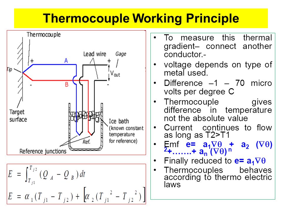
A thermocouple is comprised of at least two metals joined together to form two junctions. One is connected to the body whose temperature is to be measured; this is the hot or measuring junction. The other junction is connected to a body of known temperature; this is the cold or reference junction. Therefore the thermocouple measures unknown temperature of the body with reference to the known temperature of the other body.
Working Principle
The working principle of thermocouple is based on three effects, discovered by Seebeck, Peltier and Thomson. They are as follows:
1) Seebeck effect: The Seebeck effect states that when two different or unlike metals are joined together at two junctions, an electromotive force (emf) is generated at the two junctions. The amount of emf generated is different for different combinations of the metals.
2) Peltier effect: As per the Peltier effect, when two dissimilar metals are joined together to form two junctions, emf is generated within the circuit due to the different temperatures of the two junctions of the circuit.
3) Thomson effect: As per the Thomson effect, when two unlike metals are joined together forming two junctions, the potential exists within the circuit due to temperature gradient along the entire length of the conductors within the circuit.
In most of the cases the emf suggested by the Thomson effect is very small and it can be neglected by making proper selection of the metals. The Peltier effect plays a prominent role in the working principle of the thermocouple.
Diagrams
Thermocouples: Operating Principle
A thermocouple is a device made by two different wires joined at one end, called junction end or measuring end. The two wires are called thermoelements or legs of the thermocouple: the two thermoelements are distnguished as positive and negative ones. The other end of the thermocouple is called tail end or reference end(Figure1). The junction end is immersed in the enviroment whose temperature T2 has to be measured, which can be for instance the temperature of a furnace at about 500°C, while the tail end is held at a different temperature T1, e.g. at ambient temperature.


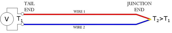
Because of the temperature difference between junction end and tail end a voltage difference can be measured between the two thermoelements at the tail end: so the thermocouple is a temperature-voltage transducer.
How it Works
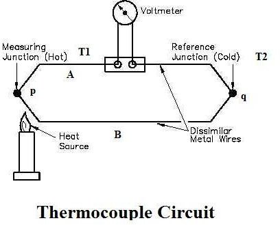
The general circuit for the working of thermocouple is shown in the figure 1 above. It comprises of two dissimilar metals, A and B. These are joined together to form two junctions, p and q, which are maintained at the temperatures T1 and T2respectively. Remember that the thermocouple cannot be formed if there are not two junctions. Since the two junctions are maintained at different temperatures the Peltier emf is generated within the circuit and it is the function of the temperatures of two junctions. If the temperature of both the junctions is same, equal and opposite emf will be generated at both junctions and the net current flowing through the junction is zero. If the junctions are maintained at different temperatures, the emf’s will not become zero and there will be a net current flowing through the circuit. The total emf flowing through this circuit depends on the metals used within the circuit as well as the temperature of the two junctions. The total emf or the current flowing through the circuit can be measured easily by the suitable device.
The device for measuring the current or emf is connected within the circuit of the thermocouple. It measures the amount of emf flowing through the circuit due to the two junctions of the two dissimilar metals maintained at different temperatures. In figure 2 the two junctions of the thermocouple and the device used for measurement of emf (potentiometer) are shown.
Now, the temperature of the reference junctions is already known, while the temperature of measuring junction is unknown. The output obtained from the thermocouple circuit is calibrated directly against the unknown temperature. Thus the voltage or current output obtained from thermocouple circuit gives the value of unknown temperature directly.
Thermocouple Temperature Limit
Thermocouple Temperature Limit Comparison

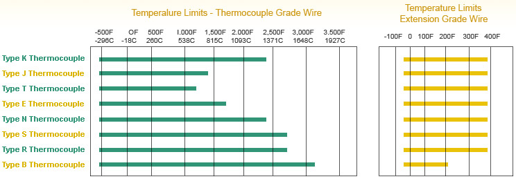
Specific Temperature Range:
Type K Thermocouple
- Thermocouple grade wire, –454 to 2,300F (–270 to 1260C)
- Extension wire, 32 to 392F (0 to 200C)
Type J Thermocouple
- Thermocouple grade wire, -346 to 1,400F (-210 to –760C)
- Extension wire, 32 to 392F (0 to 200C)
Type T Thermocouple
- Thermocouple grade wire, -454 to 700F (-270 to 370C)
- Extension wire, 32 to 392F (0 to 200C)
Type E Thermocouple
- Thermocouple grade wire, -454 to 1600F (-270 to 870C)
- Extension wire, 32 to 392F (0 to 200C)
Type N Thermocouple
- Thermocouple grade wire, -454 to 2300F (-270 to 392C)
- Extension wire, 32 to 392F (0 to 200C)
Type S Thermocouple
- Thermocouple grade wire, -58 to 2700F (-50 to 1480C)
- Extension wire, 32 to 392F (0 to 200C)
Type R Thermocouple
- Thermocouple grade wire, -58 to 2700F (-50 to 1480C)
- Extension wire, 32 to 392F (0 to 200C)
Type B Thermocouple
- Thermocouple grade wire, 32 to 3100F (0 to 1700C)
- Extension wire, 32 to 212F (0 to 100C)
Thermocouple vs. RTD
Temperature range:
First, consider the difference in temperature ranges. Noble Metal Thermocouples can reach 3,100 F, while standard RTDs have a limit of 600 F and extended range RTDs have a limit of 1,100 F.
Cost:
A plain stem thermocouple is 2 to 3 times less expensive than a plain stem RTD. A thermocouple head assembly is roughly 50% less expensive than an equivalent RTD head assembly.
Accuracy, Linearity, & Stability:
As a general rule, RTDs are more accurate than thermocouples. This is especially true at lower temperature ranges. RTDs are also more stable and have better linearity than thermocouples. If accuracy, linearity, and stability are your primary concerns and your application is within an RTD’s temperature limits, go with the RTD.
Durability:
In the sensors industry, RTDs are widely regarded as a less durable sensor when compared to thermocouples. However, REOTEMP has developed manufacturing techniques that have greatly improved the durability of our RTD sensors. These techniques make REOTEMP’s RTDs nearly equivalent to thermocouples in terms of durability.
Response Time:
RTDs cannot be grounded. For this reason, they have a slower response time than grounded thermocouples. Also, thermocouples can be placed inside a smaller diameter sheath than RTDs. A smaller sheath diameter will increase response time. For example, a grounded thermocouple inside a 1/16” dia. sheath will have a faster response time than a RTD inside a ¼” dia. sheath.
ArticleSource : Bright Hub Engineering ; Thermocoupleinfo; Slideplayer