


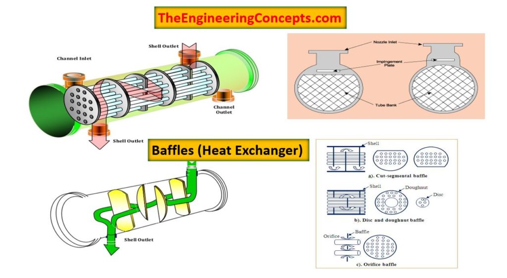
Baffles are mainly used in indudtrial process vessels or tanks such as : Static mixers / agitators, chemical reactors, heat exchangers ( mainly shell and tube heat exchangers). Baffle is actually an obstructing vane or panel mounted inside the vessel wall. Their main purpose of the vessel wall is to reduce the tangential fluid velocity (or hinders the swirling velocity of the fluid) by a mixing impeller. This enhances the mixing efficiency of the fluid within the vessel results by vigrous top to bottom mixing. In absence of baffles the time requied to achieve desired mixing is more or sufficient blending of fluids is not become possible abruptly.
In case of Heat exchangers baffles not only enhances the heat transfer coefficient but also help in supporting tube bundle inside the shell and tube heat exchanger. Baffles are placed in shell and tube heat exchanger such that they can give direction to the fluid flow. Baffle design and tolerances for heat exchangers are discussed in the standards of the Tubular Exchanger Manufacturers Association (TEMA).
Use of Baffles in Heat Exchanger
The main purpose of a baffle used in a shell and tube heat exchanger are as follows:
- It holds the tube bundle from sagging during operation helps in positioning
- It increases the fluid velocity inside the shell and tube heat exchanger which in result increases the heat transfer coefficient and overall Heat transfer rate gets increased.
In case of a static mixer, baffles are mainly used to minimize tangential component(swirling motion of the fluid) of velocity which cause vortex formation thus promote mixing.
In a chemical reactor, baffles are often attached to the interior walls to promote mixing and thus increase heat transfer and possibly chemical reaction rates.
Types of Baffles
On the basis of size, cost requirement and ability to support tube bundle are categorized as :
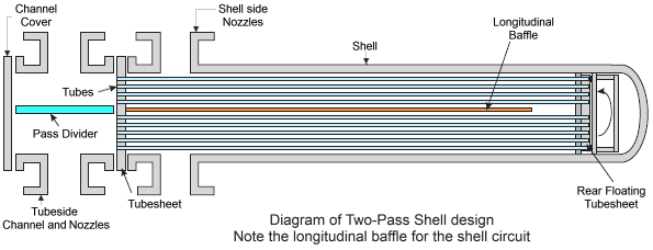
- Longitudinal Flow Baffles : Mainly used in two shell pass heat exchanger
- Impingement Baffles : It is used to protect tube bundle by direct colloding of the fluid to the tube bundle (may contain solid particles) and can damage tubes in tube bundle.
- Orifice Baffles
- Single segmental
- Double segmental
- Support/Blanking baffles
- Disc Doughnut baffles
- Deresonating (detuning) baffles used to reduce tube vibration
Longitudnal Baffle :

ImageSource : Wermac
Impingement Baffles

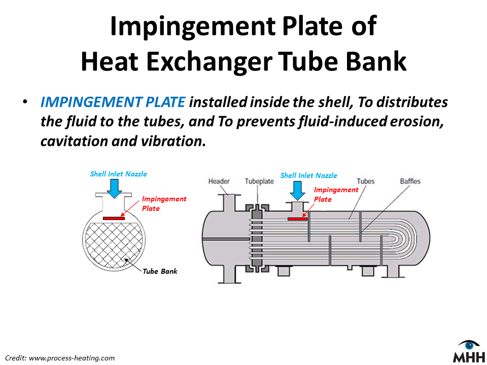
ImageSource : www.process-heating.com
Orifice Baffles / Segmental Baffle / Disc – Doughnut Baffle

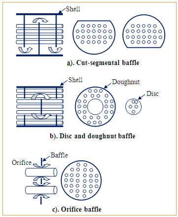
ImageSource : Nptel
Installation of Baffles
Installation of Baffles plays a vital role for better heat distribution in heat exchanger. So correct spacing, placing is important while installation. The minimum baffle spacing is the greater of 50.8 mm or one fifth of the inner shell diameter. The maximum baffle spacing is dependent on material and size of tubes. One of the important design consideration is that there should no any re – circulation zones or dead spots form – both of which are counterproductive to effective heat transfer.