


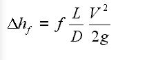
In fluid dynamics, for an incompressible, inviscid fluid flowing along a pipeline, Darcy –Weisbach equation is used to correlate a relationship among head loss, pressure loss (due to friction along the pipe ), average velocity of the fluid.

The Darcy–Weisbach equation contains a dimensionless friction factor, known as the Darcy friction factor. This is also called as Darcy–Weisbach friction factor, friction factor, resistance coefficient, or flow coefficient.
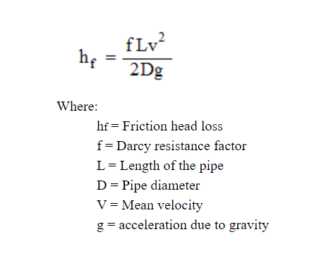
Darcy equation is extensively used to calculate head loss due to friction in turbulent flow; (Considered as Major Loss).

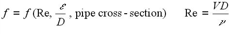
Here f (friction factor) is a function of:

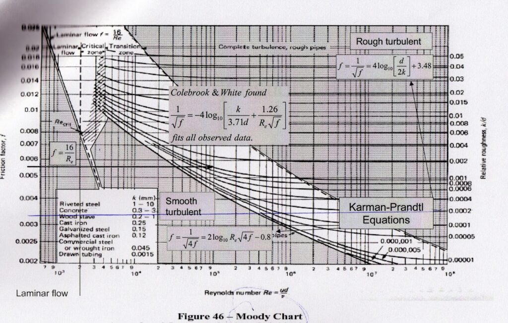
On the basis of this correlation a friction chart has been ploted termed as friction factor chart or Moody chart. This chart correlates relative roughness (e/D) of a pipe against the Reynold’s number. The blue lines plot the friction factor for flow in the wholly turbulent region of the chart, while the straight black line plots the friction factor for flow in the wholly laminar region of the chart.

The value of f, Darcy friction factor is taken from Moody Diagram.
The friction factor for laminar flow is calculated by dividing 64 by the Reynold’s number.
Friction factor (for laminar flow) = 64 / Re ; This is for circular pipes.
For Non-Circular Pipes; f=k/Re ; where k lies between 48 to 96.
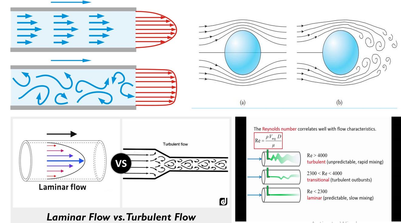
Note : When the fluid flows in a pipe and the value of Reynolds number is below 2300 the flow is considered as Laminar. Above 4000 flow is considered as Turbulent. When the value of Reynold number falls between Re 2300 to Re 4000 the flow condition is critical and considered as Transient flow. Here the flow is neither wholly laminar nor turbulent. It is a combination of the two flow conditions.
Okay Lets talk about how to calculate Losses in Pipes :
If you want to calculate the different losses in pipe, the basic approach is to write Bernoullis equation between two points, connected by a streamline. As one know that the total mechanical energy along a stream line is constant. Hence by applying energy conservation law a two different points in a pipe is :
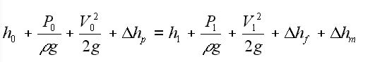

Here 0 & 1 subscript signiifies the two different points/location of a pipe. The total head at point 0 must match with the total head at point 1, adjusted for any increase in head due to pumps, losses due to pipe friction and so-called “minor losses” due to entries, exits, fittings, etc. Pump head developed is generally a function of the flow through the system, with head rise decreasing with increasing flow through the pump.
Here Friction Losses in Pipes can be correlated by Darcy-Weisbach equation i.e

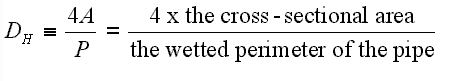
Note : Here D is termed as hydraulic diameter. In case of Non-Circular duct hydraulic diameter cab be calculated as;

Read Also : Moody Chart
ImageSource : fsl.orst.edu; pipeflow; Chemical Files