

When we talk about pump, One of the most misunderstood concept among many is the concept of pump head. And This is a frequently asked questions too in many of the technical interviews.
In this article we clear our concepts concerning what is pump head and terms related to that.

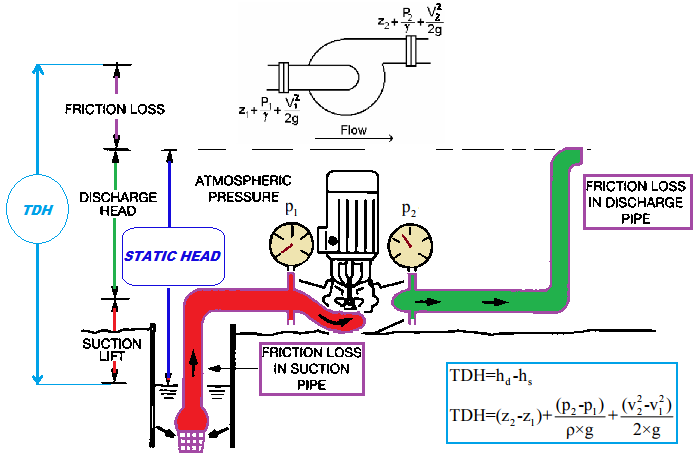
As we all know according to Bernoulli’s principle; the total mechanical energy along a stream line is always constant. Here, total mechanical energy is summation of pressure head, kinetic head and potential head.
For a fluid to flow one should know that the total mechanical energy at point 1 should be more than point 2.
Okay Lets focus more on the topic of concern.
Pump’s head is the height upto which a pump can send fluid (liquid only) to a certain height in vertical direction against gravity. The height & all depends upon pump’s efficiency. If a pump capable to produce more pressure more height it can send the fluid.

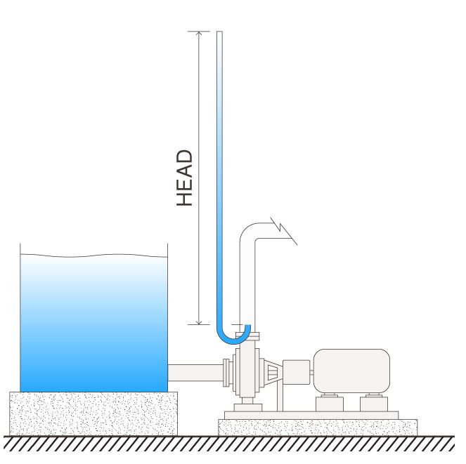
In figure 2 imagine there is pump connected to sump and in discharge there is a vertical pipe. Simply one can state: a pump’s head is the maximum height that the pump can achieve pumping against gravity.
Now the question is whether head gets affected by the suction Conditions ?

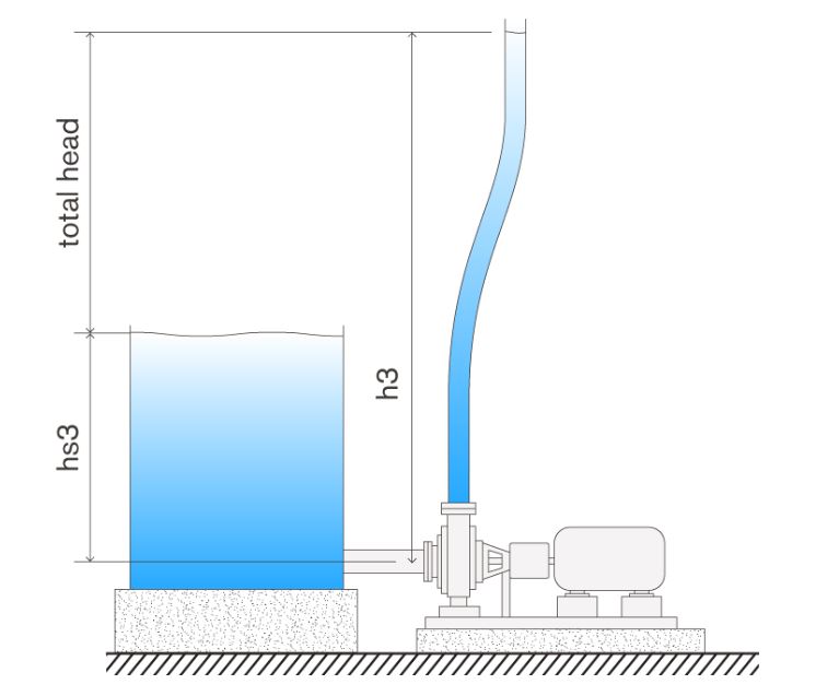
Answer is Yes. If you lower the suction level the head value decreases. Opposite is also true as you increases suction level the head value increases.
Note : Total head (difference between discharge head and suction head) remains constant in both the cases.
The head height is getting calculated assuming eye of the impeller height is zero.
Let’s discuss why it is so :
The motor of the pump simply converts electric energy into mechanical energy and that mechanical energy is used by the pump which rotates the impeller mounted on the shaft of the motor and thus impeller imparts that mechanical energy to the fluid of interest. Now the fluid having kinetic energy which is getting converted into pressure energy due to gemometrical construction of pump (simply call it volute).
As we know pressure = density of fluid * acceleration due to gravity*height.
Hence pressure is directly proportional to height.
If we raise or lower the suction level of the fluid, we are adjusting the potential energy of the fluid. The potential energy of ten foot column of water is greater than the potential energy of a five foot column of water. And this potential head helps in imparting impeller to achieve more mechanical energy as a result more head.
Hence, Increasing the level of the liquid in the suction tank will give rise to increased head, and decreasing the level will give rise to a lower head.
Another nice thing about head is it is independent of the type of fluid being pumped (assuming the viscosity is relatively low and similar to water). Whether you’re pumping water or a heavy caustic solution, the head achieved will be the same. The pressure at the discharge of the pump, however, will be higher for the heavier solution.
When you have to choose pump you may have to know two things:
1) The total head and
2) What flow rate you require.
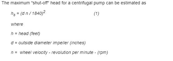
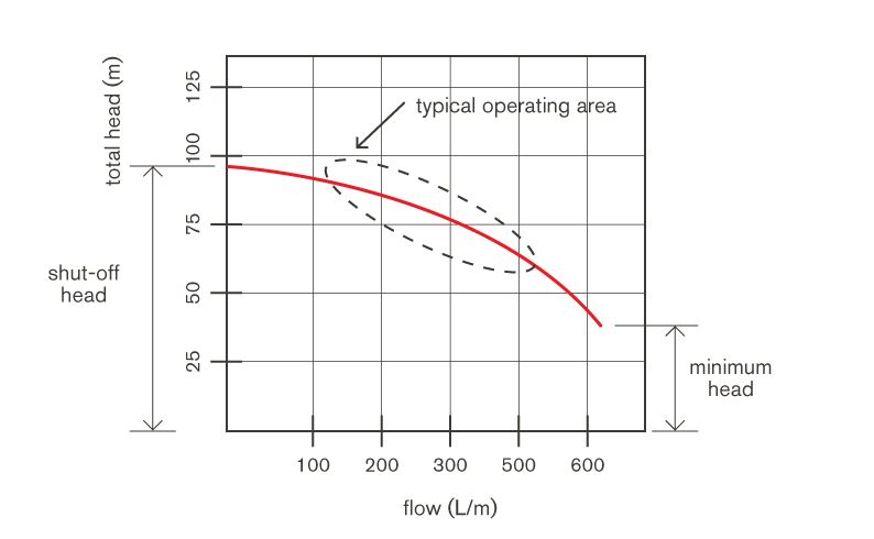
Shut Off Head :
It is defined as the maximum head achieved by the pump when the discharge is kept zero.
One can calculate Shut off head hy this correlation;

As we all know as the fluid flows through pipe there is friction into the system which hinders the fluid to achieve ideal fluid flow rate.
This friction reduces the amount of total head that the pump can produce. In fact, as the flow increases, friction increases and the total head continues to decrease. The amount of head that is lost due to friction is called “friction head” or “friction-loss”.
In a real system, the total head is the difference between the discharge head and the suction head plus the friction head and this sum will be less than the shut-off head.

Important to know friction loss depends on the length and diameters of the pipe through which the fluid flows which can be calculate by Darcy Weisbatch equation if the loss is major one.
ImageSource : Global Pumps; Engineering ToolBox; Holland Applied Technology; Amrine
ArticleReference : Global Pumps
Also Read:
Piping and Instrumentation Diagram – P&ID
How to choose betwwen PLC and DCS systems for process industries ?
Cement Manufacturing Process
Vinyl Chloride from Ethylene
Cooling Tower
Psychrometric Chart
What is Boiler ?
Venturi Flow Meter
Pitot Tube
Coriolis Mass Flow Meter
RECIPROCATING PUMP
Design of Centrifugal Pump
Valve & Its Types
Cavitation
P&ID Symbols and Notation
What is the Difference Between HMI and SCADA?
What is SCADA ? How does SCADA Works?
What is Programmable Logic Controller / PLC ?