

PID Control (Proportional+Integral+Derivative)
Overview

PID control is a feedback mechanism which is used in control system. As the name suggests, PID algorithm consists of three basic coefficients; proportional, integral and derivative which are varied to get optimal response. This type of control is also termed as three term control. By controlling the three parameters – proportional, integral and derivative we can achieve different control actions for specific work. PID is considered to be the best controller in the control system family.
In each application, coefficient of these three actions are varied to get optimal response and control. Controller input is error signal and output is given to the plant/process. Output signal of controller is generated, in such a way that, output of plant is try to achieve desired value.

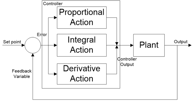
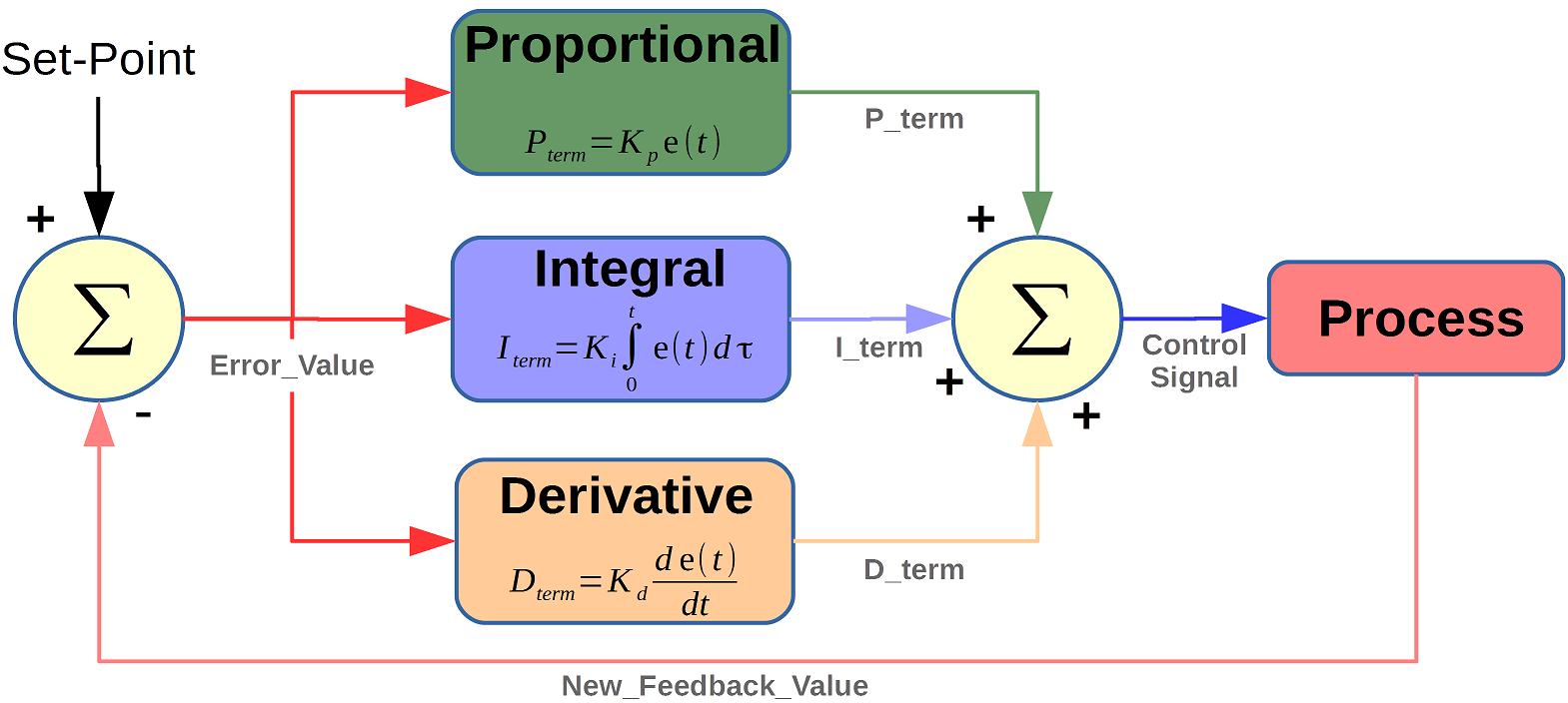
Figure : PID controller Block diagram
For PID control the actuating signal consists of proportional error signal added with derivative and integral of the error signal. Therefore, the actuating signal for PID control is

Working of PID Controller

Manual Control by Operator
In manual control, the operator may periodically read the process variable (that has to be controlled such as temperature, flow, speed, etc.) and adjust the control variable (which is to be manipulated in order to bring control variable to prescribed limits such as a heating element, flow valves, motor input, etc.). On the other hand, in automatic control, measurement and adjustment are made automatically on a continuous basis.All modern industrial controllers are of automatic type (or closed loop controllers), which are usually made to produce one or combination of control actions. These control actions include ON-OFF control, proportional control, proportional-integral control, proportional-derivative control and proportional-integral-derivative control.
With the use of low cost simple ON-OFF controller only two control states are possible, like fully ON or fully OFF. It is used for limited control application where these two control states are enough for control objective. However oscillating nature of this control limits its usage and hence it is being replaced by PID controllers.
PID controller maintains the output such that there is zero error between process variable and set point/ desired output by closed loop operations. PID uses three basic control behaviors that are explained below.
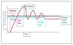
proportional band is defined as the amount of change in the controlled variable required to drive the loop output from 0 to 100%.
Gain is the ratio of output change (%) over the measured variable change (%) that caused it.
Example: If the PB is 20%, then the gain is 5. A 3% change in the error signal (setpoint- process variable) will result in a 15% change in a controller’s output, due to the proportional action. If gain is 2, then the PB is 50%.
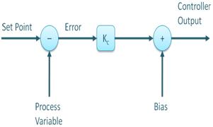
P- Controller:
Proportional or P- controller gives output which is proportional to current error e (t). It compares desired or set point with actual value or feedback process value. The resulting error is multiplied with proportional constant to get the output. If the error value is zero, then this controller output is zero.
P-Controller Response
I-Controller
Due to limitation of p-controller where there always exists an offset between the process variable and set point, I-controller is needed, which provides necessary action to eliminate the steady state error. It integrates the error over a period of time until error value reaches to zero. It holds the value to final control device at which error becomes zero.
![]()

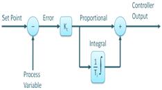
PI controller
Integral control decreases its output when negative error takes place. It limits the speed of response and affects stability of the system. Speed of the response is increased by decreasing integral gain Ki.
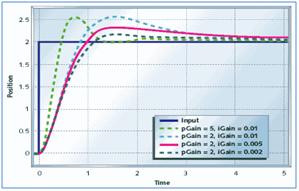
PI Controller Response
In above figure, as the gain of the I-controller decreases, steady state error also goes on decreasing. For most of the cases, PI controller is used particularly where high speed response is not required.
While using the PI controller, I-controller output is limited to somewhat range to overcome the integral wind up conditions where integral output goes on increasing even at zero error state, due to nonlinearities in the plant.
D-Controller
I-controller doesn’t have the capability to predict the future behavior of error. So it reacts normally once the set point is changed. D-controller overcomes this problem by anticipating future behavior of the error. Its output depends on rate of change of error with respect to time, multiplied by derivative constant. It gives the kick start for the output thereby increasing system response.
![]()

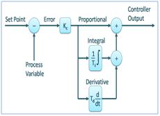
PID controller
In the above figure response of D controller is more, compared to PI controller and also settling time of output is decreased. It improves the stability of system by compensating phase lag caused by I-controller. Increasing the derivative gain increases speed of response.
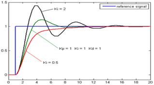
PID Controller Response
So finally we observed that by combining these three controllers, we can get the desired response for the system. Different manufactures designs different PID algorithms.
Tuning methods of PID Controller
Before the working of PID controller takes place, it must be tuned to suit with dynamics of the process to be controlled. Designers give the default values for P, I and D terms and these values couldn’t give the desired performance and sometimes leads to instability and slow control performances. Different types of tuning methods are developed to tune the PID controllers and require much attention from the operator to select best values of proportional, integral and derivative gains. Some of these are given below.
Trial and Error Method: It is a simple method of PID controller tuning. While system or controller is working, we can tune the controller. In this method, first we have to set Ki and Kd values to zero and increase proportional term (Kp) until system reaches to oscillating behavior. Once it is oscillating, adjust Ki (Integral term) so that oscillations stops and finally adjust D to get fast response.
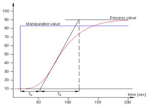
Process reaction curve technique: It is an open loop tuning technique. It produces response when a step input is applied to the system. Initially, we have to apply some control output to the system manually and have to record response curve.
After that we need to calculate slope, dead time, rise time of the curve and finally substitute these values in P, I and D equations to get the gain values of PID terms.
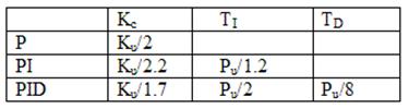
Zeigler-Nichols method: Zeigler-Nichols proposed closed loop methods for tuning the PID controller. Those are continuous cycling method and damped oscillation method. Procedures for both methods are same but oscillation behavior is different. In this, first we have to set the p-controller constant, Kp to a particular value while Ki and Kd values are zero. Proportional gain is increased till system oscillates at constant amplitude.
Gain at which system produces constant oscillations is called ultimate gain (Ku) and period of oscillations is called ultimate period (Pc). Once it is reached, we can enter the values of P, I and D in PID controller by Zeigler-Nichols table depends on the controller used like P, PI or PID, as shown below.
PID Controller Structure
PID controller consists of three terms, namely proportional, integral and derivative control. The combined operation of these three controllers gives control strategy for process control. PID controller manipulates the process variables like pressure, speed, temperature, flow, etc. Some of the applications use PID controllers in cascade networks where two or more PID’s are used to achieve control.

PID Controller Structure
Above figure shows structure of PID controller. It consists of a PID block which gives its output to process block. Process/plant consists of final control devices like actuators, control valves and other control devices to control various processes of industry/plant.
Feedback signal from the process plant is compared with a set point or reference signal u(t) and corresponding error signal e(t) is fed to the PID algorithm. According to the proportional, integral and derivative control calculations in algorithm, the controller produces combined response or controlled output which is applied to plant control devices.
All control applications don’t need all the three control elements. Combinations like PI and PD controls are very often used in practical applications.
PID control represents a significant advancement in the controls industry. It is a very effective technique for providing precise control. Although PID control is a relatively complex feature, control engineers and technicians will find that well-designed products also make it user friendly.
It is important to understand what PID control can do for your operation and to learn how to set up an effective PID control loop. While an improper setup is likely to result in unnecessary callbacks, a properly tuned PID control loop will deliver satisfaction.
Article Source : ElProCus ; Wikipedia
Photo Credit:
PID controller block diagram by wikimedia
PID controller structure by blog.opticontrols
P-controller by blog.opticontrols
P – controller response by controls.engin.umich
PI-controller by blog.opticontrols
PI- controller response by m.eet
PID controller by blog.opticontrols
PID Controller response by wikimedia
Zeigler-Nichols table by controls.engin
Read Also
Control Loop
P&ID Symbols and Notation
Venturi Flow Meter
Pitot Tube
Coriolis Mass Flow Meter
Design of Centrifugal Pump
Valve & Its Types
Cavitation
Piping and Instrumentation Diagram – P&ID