


Resistance Temperature Detector or RTD | Construction and Working Principle
The variation of resistance of the metal with the variation of the temperature is given as,


The purity of the platinum is checked by measuring R100 / R0. Because, whatever the materials actually we are using for making the RTD that should be pure. If it will not pure, it will deviate from the conventional resistance-temperature graph. So, α and β values will change depending upon the metals.
Read Also :
Venturi Flow Meter
Pitot Tube
Coriolis Mass Flow Meter
Electromagnetic Flow Meters
Hydraulic Diameter
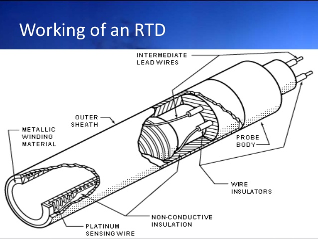
Construction of Resistance Temperature Detector or RTD
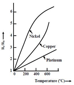
Different materials used in the construction of RTDs offer a different relationship between resistance and temperature. Temperature sensitive materials used in the construction of RTDs include platinum, nickel, and copper; platinum being the most commonly used. Important characteristics of an RTD include the temperature coefficient of resistance (TCR), the nominal resistance at 0 degrees Celsius, and the tolerance classes.
The TCR determines the relationship between the resistance and the temperature. There are no limits to the TCR that is achievable, but the most common industry standard is the platinum 3850 ppm/K. This means that the resistance of the sensor will increase 0.385 ohms per one degree Celsius increase in temperature. The nominal resistance of the sensor is the resistance that the sensor will have at 0 degrees Celsius.
The construction is typically such that the wire is wound on a form (in a coil) on notched mica cross frame to achieve small size, improving the thermal conductivity to decrease the response time and a high rate of heat transfer is obtained. In the industrial RTD’s, the coil is protected by a stainless steel sheath or a protective tube.So that, the physical strain is negligible as the wire expands and increase the length of wire with the temperature change. If the strain on the wire is increasing, then the tension increases. Due to that, the resistance of the wire will change which is undesirable.So, we don’t want to change the resistance of wire by any other unwanted changes except the temperature changes. This is also useful to RTD maintenance while the plant is in operation. Mica is placed in between the steel sheath and resistance wire for better electrical insulation. Due less strain in resistance wire, it should be carefully wound over mica sheet. The fig.2 shows the structural view of an Industrial Resistance Temperature Detector. 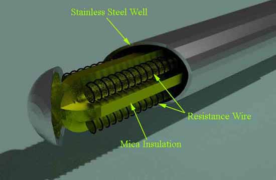

Signal Conditioning of RTD
We can get this RTD in market. But we must know the procedure how to use it and how to make the signal conditioning circuitry. So that, the lead wire errors and other calibration errors can be minimized. In this RTD, the change in resistance value is very small with respect to the temperature. So, the RTD value is measured by using a bridge circuit. By supplying the constant electric current to the bridge circuit and measuring the resulting voltage drop across the resistor, the RTD resistance can be calculated. Thereby, the temperature can be also determined. This temperature is determined by converting the RTD resistance value using a calibration expression. The different modules of RTD are shown in below figures. 


Expressions for a Three Wires RTD Circuit


Video Presentation on Resistance Temperature Detector or RTD

Limitations of RTD
In the RTD resistance, there will be an I2R power dissipation by the device itself that causes a slight heating effect. This is called as self-heating in RTD. This may also cause an erroneous reading. Thus, the electric current through the RTD resistance must be kept sufficiently low and constant to avoid self-heating.
Benefits of Thin Film RTD
There are many options when considering contact temperature measurement, including thermocouples, thermistors, and RTDs (wire wound and thin film). While thermocouples can handle very high temperatures and thermistors are inexpensive, there are many advantages of RTDs.
Some of these advantages include their accuracy, precision, long-term stability, and good hysteresis characteristics. Even beyond these, there are advantages of thin film RTDs over wire wound, including smaller dimensions, better response times, vibration resistance, and relative inexpensiveness. New advancements has even made thin film technology just as accurate as wire wound at higher temperatures ranges.
Source: Innovative Sensor Technology ; electrical4u