

What is a turbine?

Francis Turbine GIF
A turbine is a rotary mechanical device that extracts energy from a fluid flow and converts it into useful work or energy. The work produced by a turbine is used in generating electrical power when combined with a generator. A turbine is a turbomachine with at least one moving part called a rotor assembly, which is a shaft or drum with blades attached. Moving fluid acts on the blades so that they move and impart rotational energy to the rotor. Early turbine examples are windmills and waterwheels.
Gas, steam, and water turbines have a casing around the blades that contains and controls the working fluid. Credit for invention of the steam turbine is given both to Anglo-Irish engineer Sir Charles Parsons (1854–1931) for invention of the reaction turbine, and to Swedish engineer Gustaf de Laval (1845–1913) for invention of the impulse turbine. Modern steam turbines frequently employ both reaction and impulse in the same unit, typically varying the degree of reaction and impulse from the blade root to its periphery.
The word “turbine” was coined in 1822 by the French mining engineer Claude Burdin from the Latin turbo, or vortex, in a memo, “Des turbines hydrauliques ou machines rotatoires à grande vitesse”, which he submitted to the Académie royale des sciences in Paris. Benoit Fourneyron, a former student of Claude Burdin, built the first practical water turbine.
A windmill/Wind turbine is the simplest kind of turbine: a machine designed to capture some of the energy from a moving fluid (a liquid or a gas) so it can be put to use. As the wind blows past a windmill’s sails, they rotate, removing some of the wind’s kinetic energy (energy of movement) and converting it into mechanical energy that turns heavy, rotating stones inside the mill. The faster the wind blows, the more energy it contains; the faster the sails spin, the more energy is supplied to the mill. Adding more sails to the windmill or changing their design so they catch the wind better can also help to capture more of the wind’s energy. Although you may not realize it, the wind blows just a bit more slowly after it’s passed by a windmill than before—it’s given up some of its energy to the mill!

The key parts of a turbine are a set of blades that catch the moving fluid, a shaft or axle that rotates as the blades move, and some sort of machine that’s driven by the axle. In a modern wind turbine, there are typically three propeller-like blades attached to an axle that powers an electricity generator. In an ancient waterwheel, there are wooden slats that turn as the water flows under or over them, turning the axle to which the wheel is attached and usually powering some kind of milling machine.
Impulse and reaction turbines
Turbines work in two different ways described as impulse and reaction—terms that are often very confusingly described (and sometimes completely muddled up) when people try to explain them. So what’s the difference?
Impulse turbines
In an impulse turbine, a fast-moving fluid is fired through a narrow nozzle at the turbine blades to make them spin around. The blades of an impulse turbine are usually bucket-shaped so they catch the fluid and direct it off at an angle or sometimes even back the way it came (because that gives the most efficient transfer of energy from the fluid to the turbine). In an impulse turbine, the fluid is forced to hit the turbine at high speed.
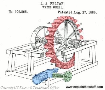

Artwork: A Pelton water wheel is an example of an impulse turbine. It spins as one or more high-pressure water jets (blue), controlled by a valve (green), fire into the buckets around the edge of the wheel (red). Lester Pelton was granted a patent for this idea in 1889, from which this drawing is taken. Artwork from US Patent 409,865: Water Wheel by Lester Pelton, courtesy of US Patent and Trademark Office.


Artwork: An impulse turbine like this works when the incoming fluid hits the buckets and bounces back again. The exact shape of the buckets and how the fluid hits them makes a big difference to how much energy the turbine can capture.
Imagine trying to make a wheel like this turn around by kicking soccer balls into its paddles. You’d need the balls to hit hard and bounce back well to get the wheel spinning—and those constant energy impulses are the key to how it works. The law of conservation of energy tells us that the energy the wheel gains, each time a ball strikes it, is equal to the energy that the ball loses—so the balls will be traveling more slowly when they bounce back. Also, Newton’s second law of motion tells us that the momentum gained by the wheel when a ball hits it is equal to the momentum lost by the ball itself; the longer a ball touches the wheel, and the harder (more forcefully) it hits, the more momentum it will transfer.
Water turbines are often based around an impulse turbine (though some do work using reaction turbines). They’re simple in design, easy to build, and cheap to maintain, not least because they don’t need to be contained inside a pipe or housing (unlike reaction turbines).
Reaction turbines
In a reaction turbine, the blades sit in a much larger volume of fluid and turn around as the fluid flows past them. A reaction turbine doesn’t change the direction of the fluid flow as drastically as an impulse turbine: it simply spins as the fluid pushes through and past its blades. Wind turbines are perhaps the most familiar examples of reaction turbines.


Photo: A typical reaction turbine from a geothermal power plant. Water or steam flows past the angled blades, pushing them around and turning the central shaft to which they’re attached. The shaft spins a generator that makes electricity. Photo by Henry Price courtesy of US Department of Energy/National Renewable Energy Laboratory (DOE/NREL).

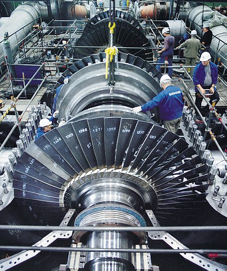
Artwork: A reaction turbine like this is much more like a propeller. The main difference is that there are more vanes in a turbine (I’ve just drawn four blades for simplicity) and often multiple sets of vanes (multiple stages), as you can see in the photos of the steam and gas turbines at the top of this page.
If an impulse turbine is a bit like kicking soccer balls, a reaction turbine is more like swimming—in reverse. Let me explain! Think of how you do freestyle (front crawl) by hauling your arms through the water, starting with each hand as far in front as you can reach and ending with a “follow through” that throws your arm well behind you. What you’re trying to achieve is to keep your hand and forearm pushing against the water for as long as possible, so you transfer as much energy as you can in each stroke. A reaction turbine is using the same idea in reverse: imagine fast-flowing water moving past you so it makes your arms and legs move and supplies energy to your body! With a reaction turbine, you want the water to touch the blades smoothly, for as long as it can, so it gives up as much energy as possible. The water isn’t hitting the blades and bouncing off, as it does in an impulse turbine: instead, the blades are moving more smoothly, “going with the flow.”
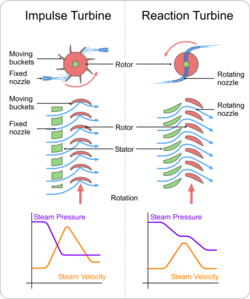

Reaction and impulse turbines comparision.
Thinking backwards


Photo: Turbines and propellers work in exactly opposite ways. Propellers use energy to make a fluid move (air, in the case of a plane, or water, in a ship or submarine); turbines harness energy when a moving fluid flows past them. Left: Propeller photo by Tech. Sgt. Justin D. Pyle courtesy of US Air Force.


Photo: Turbine blades are shaped in a similar way to propeller blades but are typically made from high-performance alloys because the fluid flowing past them can be very hot. Photo of a turbine blade exhibited at Think Tank, the science museum in Birmingham, England.
You might have noticed that wind turbines look just like giant propellers—and that’s another way to think of turbines: as propellers working in reverse. In an airplane, the engine turns the propeller at high speed, the propeller creates a backward-moving draft of air, and that’s what pushes—propels—the plane forward. With a propeller, the moving blades are driving the air; with a turbine, the air is driving the blades.
Turbines are also similar to pumps and compressors. In a pump, you have a spinning paddle wheel that sucks water in through one pipe and throws it out from another so you can move water (or another liquid) from one place to another. If you take a water pump apart, you can see the internal paddle wheel (which is called an impeller) is very similar to what you’d find inside a water turbine. The difference is that a pump uses energy to make a fluid move, while a turbine captures the energy from a moving fluid.
Turbines in action
Broadly speaking, we divide turbines into four kinds according to the type of fluid that drives them: water, wind, steam, and gas. Although all four types work in essentially the same way—spinning around as the fluid moves against them—they are subtly different and have to be engineered in very different ways. Steam turbines, for example, turn incredibly quickly because steam is produced under high-pressure. Wind turbines that make electricity turn relatively slowly (mainly for safety reasons), so they need to be huge to capture decent amounts of energy. Gas turbines need to be made from specially resilient alloys because they work at such high temperatures. Water turbines are often very big because they have to extract energy from an entire river, dammed and diverted to flow past them. They can turn relatively slowly, because is water is heavy and carries a lot of energy (because of its high mass) even when it flows at low speeds.
Water turbines


Photo: A giant Francis reaction turbine (the orange wheel at the top) being lowered into position at the Grand Coulee Dam in Washington State, USA. Water flows past the angled blades, pushing them around and turning the shaft to which they’re attached. The shaft spins an electricity generator that makes power. Photo by courtesy of US Bureau of Reclamation.
Water wheels, which date back over 2000 years to the time of the ancient Greeks, were the original water turbines. Today, the same principle is used to make electricity in hydroelectric power plants. The basic idea of hydroelectric power is that you dam a river to harness its energy. Instead of the river flowing freely downhill from its hill or mountain source toward the sea, you make it fall through a height (called a head) so it picks up speed (in other words, so its potential energy is converted to kinetic energy), then channel it through a pipe called a penstock past a turbine and generator. Hydroelectricity is effectively a three-step energy conversion:
- The river’s original potential energy (which it has because it starts from high ground) is turned into kinetic energy when the water falls through a height.
- The kinetic energy in the moving water is converted into mechanical energy by a water turbine.
- The spinning water turbine drives a generator that turns the mechanical energy into electrical energy.
Different kinds of water turbine are used depending on the geography of the area, how much water is available (the flow), and the distance over which it can be made to fall (the head). Some hydroelectric plants use bucket-like impulse turbines (typically Pelton wheels); others use Francis, Kaplan, or Deriaz reaction turbines. The type of turbine is chosen carefully to extract the maximum amount of energy from the water.
Wind turbines


These are covered in much more detail in our separate article on wind turbines.
Photo: A typical wind turbine, in Staffordshire, England. The tower is ~50m (~150ft) off the ground because the wind moves faster when it’s clear of ground-level obstructions. The rotor blades are ~15m (50ft) in diameter and, with a huge sweep, capture up to 225kW (kilowatts) of energy.
Steam turbines
Steam turbines evolved from the steam engines that changed the world in the 18th and 19th centuries. A steam engine burns coal on an open fire to release the heat it contains. The heat is used to boil water and make steam, which pushes a piston in a cylinder to power a machine such as a railroad locomotive. This is quite inefficient (it wastes energy) for a whole variety of reasons. A much better design takes the steam and channels it past the blades of a turbine, which spins around like a propeller and drives the machine as it goes.

A steam turbine with the case opened
Steam turbines were pioneered by British engineer Charles Parsons (1854–1931), who used them to power a famously speedy motorboat called Turbiniain 1889. Since then, they’ve been used in many different ways. Virtually all power plants generate electricity using steam turbines. In a coal-fired plant, coal is burned in a furnace and used to heat water to make steam that spins high-speed turbines connected to electricity generators. In a nuclear power plant, the heat that makes the steam comes from atomic reactions.
Unlike water and wind turbines, which place a single rotating turbine in the flow of liquid or gas, steam turbines have a whole series of turbines (each of which is known as a stage) arranged in a sequence inside what is effectively a closed pipe. As the steam enters the pipe, it’s channeled past each stage in turn so progressively more of its energy is extracted. If you’ve ever watched a kettle boiling, you’ll know that steam expands and moves very quickly if it’s directed through a nozzle. For that reason, steam turbines turn at very high speeds—many times faster than wind or water turbines.
Read more in in main article on steam turbines.
Gas turbines
Also Read Article on GAS TURBINE
Airplane jet engines are a bit like steam turbines in that they have multiple stages. Instead of steam, they’re driven by a mixture of the air sucked in at the front of the engine and the incredibly hot gases made by burning huge quantities of kerosene (petroleum-based fuel). Somewhat less powerful gas turbine engines are also used in modern railroad locomotives and industrial machines. See our article on jet engines for more details.


Photo: A prototype gas turbine produced for a high-efficiency power plant. Each of the metal wheels is a separate turbine stage designed to extract a bit more energy from a high-speed gas. You can see how big this turbine is by looking at the little man dressed in white sitting on the middle of the machine. Photo taken at the National Energy Technology Laboratory, Morgantown courtesy of US Department of Energy.
Article Source : ExplainThatStuff, Wikipedia