


Boundary Layer
Boundary Layer
In general, when a fluid flows over a stationary surface, e.g. the flat plate, the bed of a river, or the wall of a pipe, the fluid touching the surface is brought to rest by the shear stress to at the wall. The region in which flow adjusts from zero velocity at the wall to a maximum in the main stream of the flow is termed the boundary layer. The concept of boundary layers is of importance in all of viscous fluid dynamics and also in the theory of heat transfer.
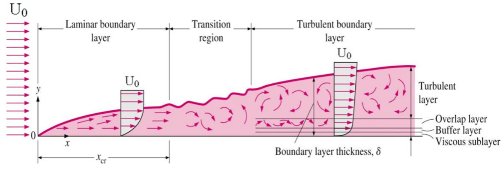
Basic characteristics of all laminar and turbulent boundary layers are shown in the developing flow over a flat plate. The stages of the formation of the boundary layer are shown in the figure below:


Boundary layer on flat plate
Boundary layers may be either laminar, or turbulent depending on the value of the Reynolds number.
The Reynolds number is the ratio of inertia forces to viscous forces and is a convenient parameter for predicting if a flow condition will be laminar or turbulent. It is defined as

in which V is the mean flow velocity, D a characteristic linear dimension, ρ fluid density, μ dynamic viscosity, and ν kinematic viscosity.
For lower Reynolds numbers, the boundary layer is laminar and the streamwise velocity changes uniformly as one moves away from the wall, as shown on the left side of the figure. As the Reynolds number increases (with x) the flow becomes unstable and finally for higher Reynolds numbers, the boundary layer is turbulent and the streamwise velocity is characterized by unsteady (changing with time) swirling flows inside the boundary layer.
Transition from laminar to turbulent boundary layer occurs when Reynolds number at x exceeds Rex ~ 500,000. Transition may occur earlier, but it is dependent especially on the surface roughness. The turbulent boundary layer thickens more rapidly than the laminar boundary layer as a result of increased shear stress at the body surface.
The external flow reacts to the edge of the boundary layer just as it would to the physical surface of an object. So the boundary layer gives any object an “effective” shape which is usually slightly different from the physical shape. We define the thickness of the boundary layer as the distance from the wall to the point where the velocity is 99% of the “free stream” velocity.
To make things more confusing, the boundary layer may lift off or “separate” from the body and create an effective shape much different from the physical shape. This happens because the flow in the boundary has very low energy (relative to the free stream) and is more easily driven by changes in pressure.
Special reference: Schlichting Herrmann, Gersten Klaus. Boundary-Layer Theory, Springer-Verlag Berlin Heidelberg, 2000, ISBN: 978-3-540-66270-9


Viscosity of Water – 16MPa


Density of Water – 16 MPa
Boundary Layer Thickness
We define the thickness of the boundary layer as the distance from the wall to the point where the velocity is 99% of the “free stream” velocity. For laminar boundary layers over a flat plate, the Blasius solution of the flow governing equations gives:

where Rex is the Reynolds number based on the length of the plate.
For a turbulent flow the boundary layer thickness is given by:

This equation was derived with several assumptions. The turbulent boundary layer thickness formula assumes that the flow is turbulent right from the start of the boundary layer.
Source Article : Nuclear Power
Image Source : Nuclear Power
References:
- J. R. Lamarsh, Introduction to Nuclear Reactor Theory, 2nd ed., Addison-Wesley, Reading, MA (1983).
- J. R. Lamarsh, A. J. Baratta, Introduction to Nuclear Engineering, 3d ed., Prentice-Hall, 2001, ISBN: 0-201-82498-1.
- W. M. Stacey, Nuclear Reactor Physics, John Wiley & Sons, 2001, ISBN: 0- 471-39127-1.
- Glasstone, Sesonske. Nuclear Reactor Engineering: Reactor Systems Engineering, Springer; 4th edition, 1994, ISBN: 978-0412985317
- Todreas Neil E., Kazimi Mujid S. Nuclear Systems Volume I: Thermal Hydraulic Fundamentals, Second Edition. CRC Press; 2 edition, 2012, ISBN: 978-0415802871
- Zohuri B., McDaniel P. Thermodynamics in Nuclear Power Plant Systems. Springer; 2015, ISBN: 978-3-319-13419-2
- Moran Michal J., Shapiro Howard N. Fundamentals of Engineering Thermodynamics, Fifth Edition, John Wiley & Sons, 2006, ISBN: 978-0-470-03037-0
- Kleinstreuer C. Modern Fluid Dynamics. Springer, 2010, ISBN 978-1-4020-8670-0.
- U.S. Department of Energy, THERMODYNAMICS, HEAT TRANSFER, AND FLUID FLOW. DOE Fundamentals Handbook, Volume 1, 2 and 3. June 1992.
- White Frank M., Fluid Mechanics, McGraw-Hill Education, 7th edition, February, 2010, ISBN: 978-0077422417