


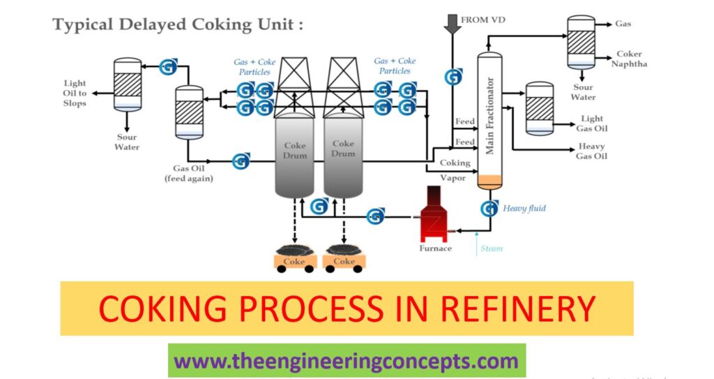
What is Coking Process in Refinery?
Coking process is nothing but a refinery unit operation to upgrade vacuum residue from bottom of vacuum distillation column into more valuable products using thermal cracking. The objective of the process is to increase the yield of distillate products. Vacuum residue is also called as bottom of the barrel.
Article Written By : C Saravanakumar
There are several technologies used to upgrade vacuum residue into valuable products.
Types of coking process
- Delayed Coking.
- Fluid Coking.
- Flexi Coking.
In this article we will see Delayed Coker unit.
What is Delayed Coking?
Delayed coking is a process, which is used to convert vacuum residue feed from the bottom of the vacuum distillation column into valuable products leaving behind coke as byproduct. In the Delayed Coker unit, Vaccum residue is rapidly heated in heater and thermally cracked in coke drums under certain operating conditions of pressure and temperature. Delayed coker products are Fuel gas, LPG, Naphtha, Light coker gas oil, Heavy coker gas oil and Coke. The products from Delayed coker are sent to downstream units for further upgrading.
Also Read : Fluid Coking & Flexi Coking
There are different types of coke produced based on feed characteristics and operating conditions.
Types of coke:
- Anode grade coke- To produce anode in aluminum manufacturing process.
- Needle coke- It is used for graphide electrode manufacturing.
- Fuel grade coke.- It is used as fuel for steam generators.
Why it is called Delayed Coking?
Vacuum residue Feed is heated in heater and sent to coke drum where the coke is formed. Coke formation is delayed until it reaches the coke drum. In the heater velocity steam is added to increase the velocity of the feed to ensure that feed is not choked inside the heater tubes.
Delayed Coker unit consists of several Sections:
- Feed Section
- Heater and Coke drum
- Fractionator
- Blowdown Section
- Gas section.
- Feed Section:
Feed for the Delayed Coker unit is vacuum residue which coming from vacuum distillation column bottom. Feed is preheated using it’s products in several heat exchangers and sent to fractionator bottom. Fractionator is acting as feed surge drum as well as distillation column. Preheated feed from fractionator bottom is sent to heater.
- Heater and Coke Drum:
Heater and the coke drum are the heart of the delayed coker process. Feed from the fractionator bottom is sent to heater where it is heated to around 500 0C. To delay the coking process inside the heater tubes and to prevent the fouling of heater tubes steam or condensate is injected inside the heater tubes. In Delayed Coker each heater outlet is connected to pair of coke drums. One drum will be under coking process whereas the other drum will be under decoking process. Hot feed enters the empty drum cracking reaction takes place at certain temperature and pressure. Cracked hot gas leaves the coke drum from the top and the solid coke is formed inside the drum. Once the drum is full up to the predetermined level, hot liquid feed is switched to the other drum and the filled drum is ready to be emptied which is called decoking.
Decoking is nothing but removing the coke from the coke drum through several steps. First steam is introduced to remove the hydrocarbons from the coke drum and then quenched using water to cool the coke in the drum before coke is being removed.
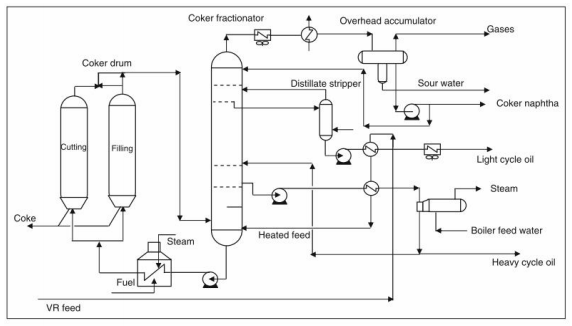
3. Fractionator:
Cracked Vapor from the Coke drum is sent to fractionator. Fractionator is used to separate the coke drum vapor into several products. As the coke drum vapor travels up the fractionator it is cooled at different stages and the various products are taken out from fractionator as side cuts. The products are heavy coker gas oil, light coker gas oil, kerosene, naphtha, LPG and Fuel gas. Naphtha, LPG, Fuel gas are taken from the top of the fractionator.
4. Gas Section:
Gas section consists of wet gas compressor, Absorber, Stripper and Debutanizer. Wet gas from fractionator overhead drum is sent to compressor where the gas is compressed in several stages. After every stage of compression gas is cooled and the water and heavier contents are condensed. Compressed gas after cooling from second stage compression is sent to Absorber where it is counter contacted with stabilized naphtha to remove the heavier content from the fuel gas. Fuel gas from absorber is sent to secondary absorber which is called as sponge absorber where it is contacted with sponge oil which is light coker gas oil to further remove C4 & C5 from fuel gas. Fuel gas coming out of secondary absorber will have H2S which is removed in amine absorber before being sent into refinery fuel gas header.
Absorber bottom is sent to stripper where lighter is stripped off using reboiler. Stripper bottom is sent to debutanizer. In the debutanizer C3 and C4 is removed at the top which is called as LPG. LPG is further treated in amine absorber to remove the H2S. Stabilized naphtha is withdrawn from the bottom of the debutanizer which is sent to downstream unit for further processing.
Blowdown section:
The purpose of blowdown section is to recover the hydrocarbons from the coke drum during decoking for further processing. Decoking the coke drum has several steps like steam out, water quenching and drum reheat. During these process hydrocarbons generated from the coke drum is sent to blowdown column from where vapor is separated at the top of the column and sent to compressor and the liquid from the bottom of the blowdown column is sent to coke drum overhead line to quench the coke drum vapor.

ImageSource : https://ceng.tu.edu.iq/