


Thermodynamic Cycle
The Thermodynamic cycle is a system which involves sequential thermodynamic processes, transfer of heat, work expansion or compression during varying pressure, temperature and other state variable and at the end, the system comes to its initial state.
Aricle written By : Pallavi Wankhede
During the cycle, the various types of thermodynamic processes involved are:
- Adiabatic: there is no energy transfer outside the system.
- Isothermal: the temperature remains constant where the reaction takes place in a cycle.
- Isobaric: the pressure remains constant in a cycle where the reaction takes place.
- Isochoric: reaction takes place at constant volume in a cycle.
- Isentropic: the entropy remains constant in a part of the cycle where the reaction takes place.
- Isenthalpic: the enthalpy or change in enthalpy remains constant where the reaction takes place.
- Polytropic: It involves multiple expansion and compression processes during heat transfer.
- Reversible: the entropy production is zero.
The thermodynamic cycle is primarily divided into two main cycles, power cycles and heat pump cycles, Where Power cycle convert heat input into mechanical work output, while heat cycle transfer heat from low temperature to high temperatures with the help of input as the mechanical work.
Thermodynamic Power Cycles are used to model the various types of heat engines. The cycle has two parts internal combustion engines and external combustion engines.
The internal combustion engine involves the Otto cycle and diesel cycle.
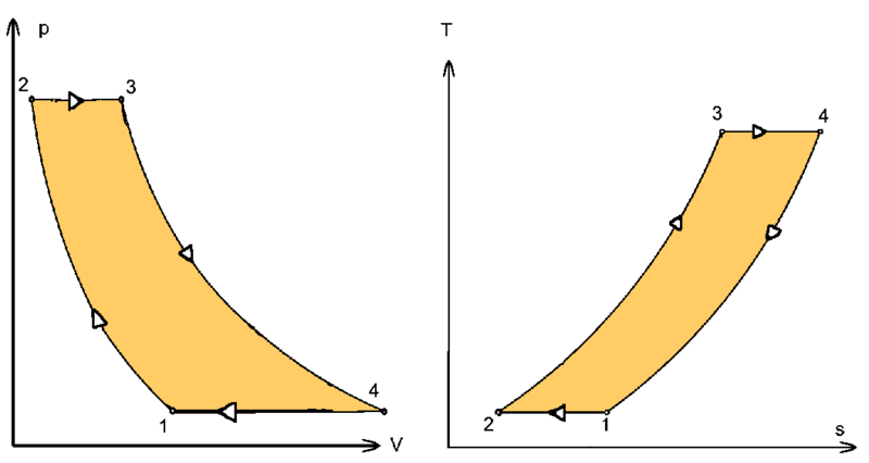
1. Otto Cycle: This cycle is used to model the gasoline engine. It also describes the function of a typical spark ignition piston engine. It involves the changes in the mass of gas with respect to change in pressure, temperature, volume, the addition of heat, and the removal of heat. The mass of gas is usually fluid within the cylinder and it is also called a system in this cycle. It considers both the changes, the changes in the system due to thermodynamic properties and the changes on the environment due to the system’s effect. The Otto cycle describes how much effect needs to be produced to get enough work from the system that needs to propel an automobile and its respected holder.
The sequence of operation for the Otto cycle is:
Part 1-2: isentropic
Part 2-3: isochoric
Part 3-4: isentropic
Part 4-1: isochoric

2. Diesel Cycle: This cycle is used to model the diesel engine. The diesel cycle is in complete contrast to the Otto cycle. It describes the combustion process of a reciprocating internal combustion engine. The fuel is ignited with the help of heat generated during the compression of air in the combustion chamber where then fuel is injected. The Diesel engine is used in aircraft, automobiles, power generation, diesel-electric locomotives and both surfaces of ships and submarines.
The sequence of operation for the diesel cycle is:
Part 1-2: Adiabatic
Part 2-3: Isobaric
Part 3-4: Adiabatic
Part 4-1: Isochoric

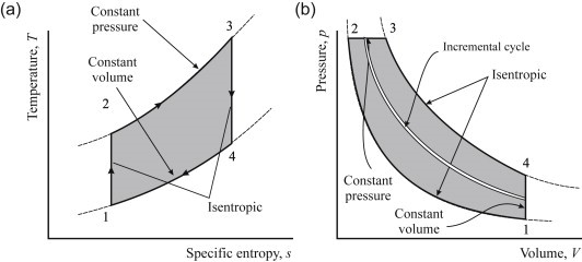
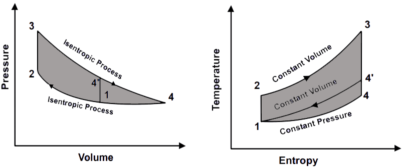
3. Dual Cycle: This cycle is a combination of two cycles, the Otto cycle, and the diesel cycle. It involves the addition of heat partly at the isochoric and isobaric reaction. This gives more time to fuel for complete combustion. This cycle is used only for diesel and hot spot engines due to the lagging characteristics of fuel.
The sequence of operation for the dual cycle is:
Part 1-2: Isentropic Compression
Part 2-3: Addition of heat at Constant Volume
Part 3-4: Isentropic expansion
Part 4-5: Rejection of heat at constant volume
Part 5-1: Isochoric
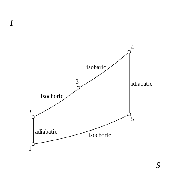
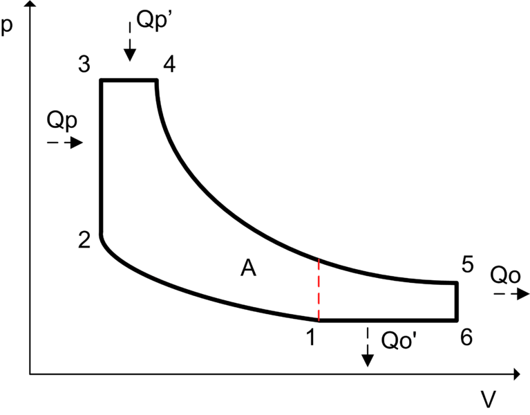
4. Atkinson Cycle: It is a type of internal combustion engine. The cycle is designed to provide efficiency at the expense of power density. Its application has been used in modern automobiles such as hybrid electric cars, Toyota Prius. Analysis in the Atkinson cycle gives the idea of a good economy for the engine.
The sequence of operation for the Atkinson cycle is:
Part 1-2: Isentropic (adiabatic compression)
Part 2-3: Isochoric heating
Part 3-4: Isobaric heating
Part 4-5: Isentropic Expansion
Part 5-6: Isochoric cooling
Part 6-1: Isobaric Cooling


The external combustion engine involves the Brayton cycle, Rankine cycle, Stirling cycle, and Ericsson cycle.
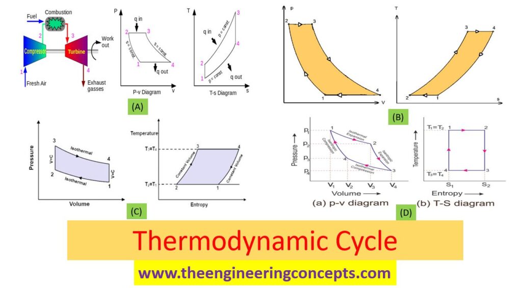
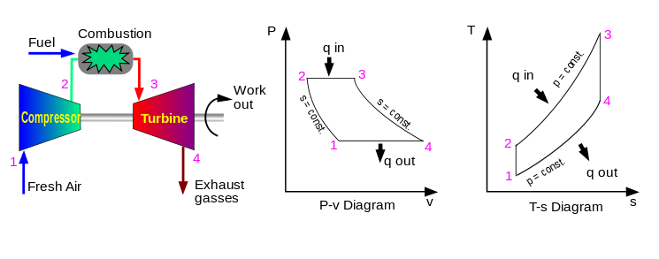
5. Brayton Cycle: This cycle is used to model the gas turbines and jet engines. It describes the working of a constant pressure heat engine. The engine formed with the help of Brayton cycle is also called a Brayton engine which uses piston compressor and piston expander. This cycle is usually run as an open system, while exhaust gases are further reused in the intake and enabling the analysis of a closed system. On the other hand, Brayton cycle is open to atmosphere and used in IC (internal combustion) chamber and a closed type cycle is used in heat exchanger.
The sequence of operation for Brayton cycle is:
Part 1-2: Adiabatic (compression)
Part 2-3: Isobaric (heat addition)
Part 3-4: Adiabatic (expansion)
Part 4-1: Isobaric (heat rejection)

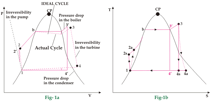
6. Rankine Cycle: This cycle is used to model the steam turbines. It is also used to study the performance of the reciprocating systems. This is an idealized thermodynamic cycle of heat engine that converts heat into mechanical work during phase change reaction where friction losses are neglected. The heat is supplied externally to a closed loop of a cycle, where water is used as a working fluid. The Rankine cycle is mostly found in the thermal power generation plants which generate the power.
The sequence of operation for the Rankine cycle is:
Part 1-2: Adiabatic
Part 2-3: Isobaric
Part 3-4: Adiabatic
Part 4-1: Isobaric

7. Ericsson Cycle: This cycle is used to model the hot air engines. Ericsson engine is based on this cycle; the engine is also known as an external combustion engine as it is heated externally. The Ericsson engine has a regenerator between the compressor and expander to improve efficiency. The cycle can be run in an open or closed cycle. The expansion takes place simultaneously with compression, on the opposite side of the piston.
The sequence of operation for the Ericsson cycle is:
Part 1-2: Isothermal
Part 2-3: Isobaric
Part 3-4: Isothermal
Part 4-1: Isobaric

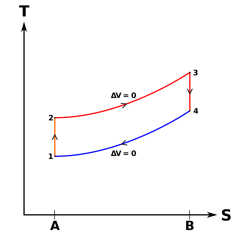
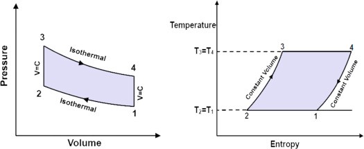
8. Stirling Cycle: This cycle is used to model hot air engines. The cycle is reversible which states that if it is supplied with mechanical power, it can work as a heat pump for heating or cooling and for cryogenic cooling as well. It is also called a closed regenerative cycle with a working fluid as gas.
The sequence of operation for the Stirling cycle is:
Part 1-2: Isothermal
Part 2-3: Isochoric
Part 3-4: Isothermal
Part 4-1: Isochoric

The heat pump cycle involves Carnot Cycle.
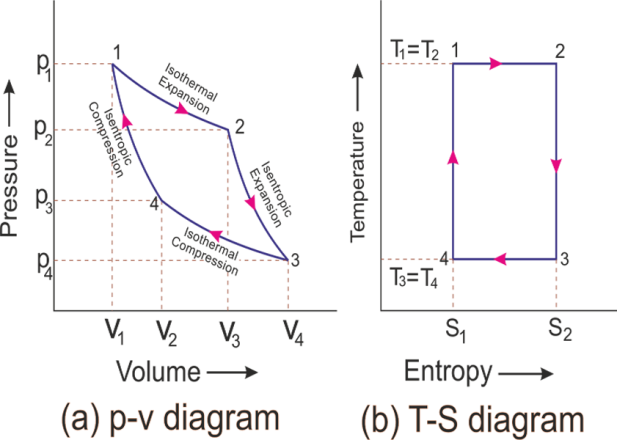
9. Carnot Cycle (Ideal Cycle): This cycle is used to model the Carnot heat engine. This is an ideal cycle that provides an upper limit on the efficiency that any classical thermodynamic engine can achieve during the conversion of heat into work, or conversely the efficiency of a refrigeration system in creating a temperature difference by the application of work to the system.
The sequence of operation for the Carnot cycle is:
Part 1-2: Isothermal Expansion
Part 2-3: Isentropic Expansion
Part 3-4: Isothermal Compression
Part 4-1: Isentropic Compression

Content Source:
https://en.wikipedia.org/; https://chem.libretexts.org/;
Image Source:
https://en.wikipedia.org/; http://web.mit.edu/; https://www.sciencedirect.com/; https://www.electrical4u.com/; https://www.mechanicaltutorial.com/;
Also Read:
Thermosyphon Reboiler
Piping and Instrumentation Diagram – P&ID
How to choose betwwen PLC and DCS systems for process industries ?
Cement Manufacturing Process
Vinyl Chloride from Ethylene
Cooling Tower
Psychrometric Chart
What is Boiler ?
Venturi Flow Meter
Pitot Tube
Coriolis Mass Flow Meter
RECIPROCATING PUMP
Design of Centrifugal Pump
Valve & Its Types
Cavitation
P&ID Symbols and Notation
What is the Difference Between HMI and SCADA?
What is SCADA ? How does SCADA Works?
What is Programmable Logic Controller / PLC ?
What is Distributed Control Systems (DCS) ?
Heat Exchanger Temperature Control
What is Compressor Surge ?
Ejectors & Its Working Principle
Desuperheater
Three Phase Seperator