


FLUID COKING
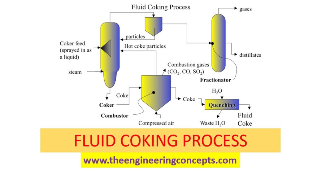
Fluid coking is a process which is used to process vacuum residue into valuable products. Fluid coking is like a fluid catalytic cracking. In fluid catalytic cracking catalyst is circulated whereas in fluid coking, coke particles are circulated and maintained in fluidized condition. Fluid coking also thermal cracking process. In fluid coking process the produced coke is burnt to generate heat for thermal cracking process.
Article Written By : C Saravanakumar

Fluid Coking unit consists two important sections:
- Reactor
- Burner
- Fractionator
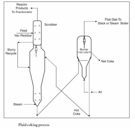
Reactor:
Vaccum residue feed first passed through scrubber. The purpose is to scrub the coke particles carried over with finished products. Vacuum residue feed is sprayed into the scrubber and then vaccum residue goes to Reactor where cracking reaction takes place at around 480 deg oC to 590 Deg oC with the help of heat provided by hot coke coming from burner. Reactor is the heart of the fluid coking process. Hot Coke particles from the burner are maintained in fluidized condition. It is ensured that feed and coke particles are mixed well to have better reaction inside the reactor. During cracking reaction, coke is formed inside the reactor. This is cold coke which is transferred to burner. Steam is injected at the bottom of the reactor to promote the fluidization of particles in the bed as well as to ensure that vapor products formed in the reactor are pushed upward through the reactor.
Also Read :
Burner:
The solid coke particles formed at the bottom of the reactor is transferred to burner where the coke particles are heated with air around 500 deg oc to 750 deg oc. The hot coke particles are then recirculated to fluidized bed zone of the reactor where it is maintained in fluidized condition. Small amount of coke is purged out from the burner continuously.
Fractionator:
Hot vapor from the scrubber goes to fractionator where it is cooled at different stages and converted to various products are taken out from fractionator as side cuts. Lighters from the overhead drum top sent to gas section where it is separated into fuel gas and LPG.
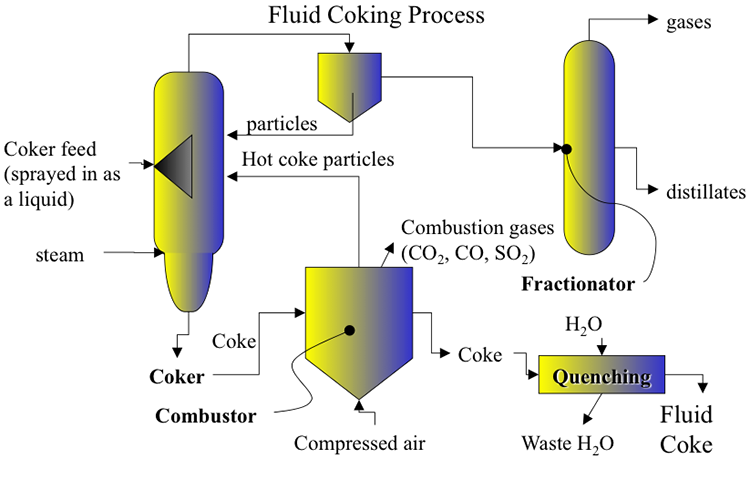

Image Source : ceng.tu.edu.iq; e-education.psu.edu